Project Explorer
This is a tree-style explorer. It contains a number of items, and the values in this tree are what get saved to the input. Data created in the Workspace or in the Library must be copied into the Project Explorer to be saved without data loss.
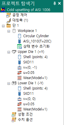
Title
Double-clicking Title opens the Process Information dialog.
Process Control
Double-clicking Process Control opens the Process Control dialog.
Symmetry
2D axisymmetric- Axis of symmetry (1)2D plane strain- Axis of symmetry (0)3D- Planes of symmetry (n); the number of planes of symmetry defined by the user is shown, and double-clicking opens the Symmetric Plane definition dialog.
Stage
Under the Stage item, the Workpiece, Die, Forming, Stage Numerical and special-process items are listed.
Selecting a Stage or one of its sub-items activates that stage in the Pre view.
Context menu (Stage)
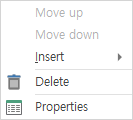
Move up - Disabled when the first stage is selected. Clicking Move up moves the selected stage upward. Move down - Disabled when the last stage is selected. Clicking Move down moves the selected stage downward.
Delete - Removes the selected stage.
Properties - Shows/hides the Properties pane.
Context menu (Stage > Insert)
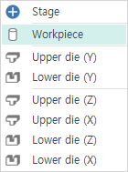
Stage- Adds a new stage in front of the selected stage.Workpiece- Adds a workpiece to the selected stage. Since the workpiece does not disappear during forming, a workpiece is added to every stage.Upper die (Y)- Adds an upper die in the Y direction to the selected stage.Lower die (Y)- Adds a lower die in the Y direction to the selected stage.Upper die (Z)- Adds an upper die in the Z direction to the selected stage.Upper die (X)- Adds an upper die in the X direction to the selected stage.Lower die (Z)- Adds a lower die in the Z direction to the selected stage.Lower die (X)- Adds a lower die in the X direction to the selected stage.
Workpiece
The workpiece item lists the shape, the material, the state-variable initialization and other options.
Context menu (Workpiece)
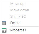
Move up- Disabled when the first workpiece is selected. ClickingMove upmoves the selected workpiece upward.Move down- Disabled when the last workpiece is selected. ClickingMove downmoves the selected workpiece downward.Delete- Removes the selected workpiece.Properties- Shows/hides the Properties pane.
Die
The die item lists the shape, the material, the press, the friction and other options.
Context menu (Die)
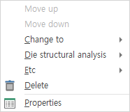
Move up- Disabled when the first die is selected. ClickingMove upmoves the selected die upward.Move down- Disabled when the last die is selected. ClickingMove downmoves the selected die downward.Delete- Removes the selected die.Properties- Shows/hides the Properties pane.
Context menu (Die > Change to)
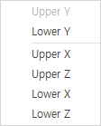
Upper Y- Disabled if the die is already an upper die in the Y direction. ClickingUpper Ychanges it to an upper die in the Y direction.Lower Y- Disabled if the die is already a lower die in the Y direction. ClickingLower Ychanges it to a lower die in the Y direction.Upper X- Disabled if the die is already an upper die in the Y direction. ClickingUpper Xchanges it to an upper die in the X direction.Upper Z- Disabled if the die is already an upper die in the Z direction. ClickingUpper Zchanges it to an upper die in the Z direction.Lower X- Disabled if the die is already a lower die in the X direction. ClickingLower Xchanges it to a lower die in the X direction.Lower Z- Disabled if the die is already a lower die in the Z direction. ClickingLower Zchanges it to a lower die in the Z direction.
Context menu (Die > Die structural analysis)
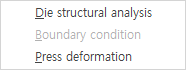
Die structural analysis- Opens the Die Structural Analysis dialog, where the die structural analysis options during forming are set.Boundary condition- Enabled for three-dimensional models. Opens the Boundary Condition dialog, where the boundary conditions of the die are entered.Press deformation- Opens the Press Deformation dialog, where the press deformation options during die structural analysis are set.
Context menu (Die > Etc)
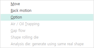
Move- Opens the dialog with the option to forcibly move the die from its current position.Back motion- Opens the dialog for configuring the backward motion of the die after the stroke set in Forming is completed.Option- Opens the dialog for setting the other options of the die.Air / Oil Trapping- Enabled for three-dimensional models. Opens the dialog used when analyzing under-fill caused by trapped air or oil.Gap flow- Enabled for three-dimensional models. Opens the dialog for setting the gap between dies.Shape rolling die- Enabled for three-dimensional shape rolling processes. Opens the dialog for defining the rolling rolls.Analysis die generate using same real shape- Enabled for three-dimensional models. Modeling is normally done to match the actual die, but this is unfavorable for the analysis, so a separate analysis die is generated in the pre-processor. When this item is checked, the analysis die is generated with the same shape as the actual die.
Forming
Double-clicking Forming opens the Forming dialog.
Stage Numerical
Double-clicking Stage Numerical opens the Stage Numerical dialog.
Shape
Selecting a shape displays its outline in the Pre view.
Context menu (Shell)
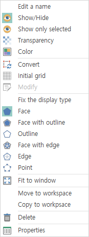
Edit a name- Opens the dialog for renaming the selected object.Show/Hide- Shows/hides the selected object in the Pre view.Show only selected- Shows only the selected object in the Pre view. All other objects are hidden.Transparency- Opens the dialog for adjusting the transparency of the selected object.Color- Opens the dialog for adjusting the color of the selected object.Convert- Enabled for two-dimensional models. Converts an object created with Auto Shape into a point-list format.Initial grid- Enabled for two-dimensional models of the Auto Shapeboxtype. Opens the dialog for setting the initial grid.Modify- Enabled when the shell is two-dimensional and in point-list format. Opens the dialog for adjusting the positions of the points, or for increasing or decreasing the number of points to create a different shape.Fix the display type- For a shell with this option checked, the display option is locked and commands fromRibbon > View tab > Render groupare not applied to it.Face- Renders the faces of the selected model filled with the configured color.Face with outline- Renders the faces of the selected model filled with the configured color and also shows the outline.Outline- Renders only the outline of the selected model.Face with edge- Renders the faces of the selected model filled with the configured color and shows the edges of all elements that define the faces.Edge- Renders the edges of all elements that define the faces of the selected model.Point- Renders only the points of the selected model.Fit to window- Fits the selected model to the window.Move to workspace- Moves the selected model to the Workspace.Copy to workspace- Copies the selected model to the Workspace.Delete- Removes the selected model.Properties- Shows/hides the Properties pane.
Basic objects
In general, double-clicking an item opens a dialog in which the properties of that object can be modified.
Context menu (Object)
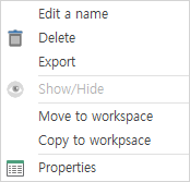
Edit a name- Opens the dialog for renaming the selected object.Delete- Removes the selected object.Export- Saves the selected object as a library file.Show/Hide- Enabled only for objects that are rendered graphically in the Pre view. Shows/hides the selected object.Move to workspace- Moves the selected object to the Workspace.Copy to workspace- Copies the selected object to the Workspace.Properties- Shows/hides the Properties pane.