Process Information Dialog
Purpose
This dialog defines the basic conditions of a forming process. It defines the options to be calculated during analysis.
How to open
- Click
Newin the Backstage view. - Double-click the top-level item (title) in the Project Explorer.
Dialog layout
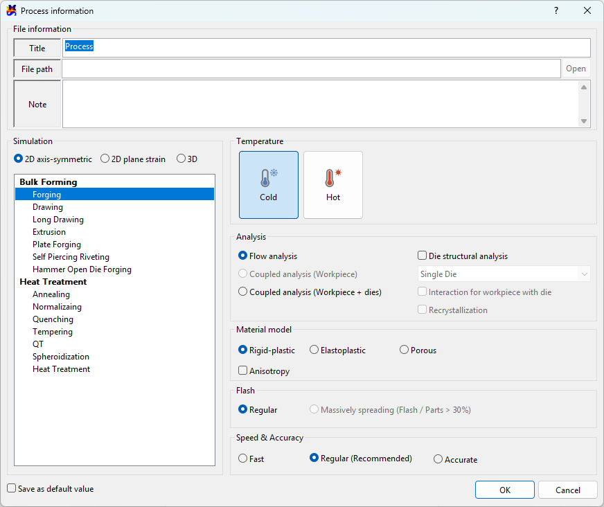
Input information
File information
Title
Enter the title of the current project.
File path
The saved file path is displayed. It is blank initially.
Note
Enter additional information about the process.
Simulation
Defines 2D axisymmetric, 2D plane strain, and 3D problems. Depending on the option, the user's license is checked and the list of projects that can be created is displayed.
Temperature
Distinguishes between Cold forging (room temperature) and Hot forging.
The initial value when creating a project changes depending on the selected ambient temperature type.
Analysis
Indicates the type of analysis.
Flow analysis- Used when analyzing with an emphasis on material deformation.Non-isothermal analysis (Workpiece)- Enabled for3Dcases. Used for flow analysis + considering the temperature change of the workpiece.Non-isothermal analysis (Workpiece + Die)- Used for flow analysis + considering the temperature change of the workpiece and dies.
Die structural analysis
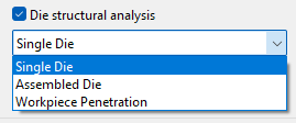
When this Die structural analysis is checked, a die structural analysis is performed during forming analysis to calculate the stress acting on the die.
Single die: Inter-die linkage not considered (refer to 2D tutorial part2 ex. 13)Assembled die: Inter-die linkage considered (refer to 3D tutorial part2 ex.11)Workpiece penetration: Considers allowing the workpiece to penetrate into the die by the amount of die deformation
Interaction between workpiece and die
This is an option for the contact boundary with the die during workpiece flow analysis. If checked, the die boundary deformed by the die structural analysis is used; if unchecked, the entered rigid die boundary is used as is.
Recrystallization
If checked, the microstructure size and hardness of the material are predicted.
Material model
Rigid-plastic- In metal forming, when the elastic deformation is very small compared to the plastic deformation and is therefore ignored, it is called rigid-plastic.Elastoplastic- Both elastic and plastic deformation are considered simultaneously. (Springback prediction)Porous- Select this for powder materials.Anisotropic- Check this when considering material anisotropy during elastoplastic analysis.
Flash
Regular- default valueMassive (flash area / workpiece area > 30%)- A function that prevents excessive elements from being generated in unnecessary areas when a large amount of flash occurs in 3D (e.g., crankshaft forging process)
Speed & Accuracy
The default values change when creating a project.
Fast- Reduces the number of automatically generated elements and solution steps below the default.Regular- Uses the default values.Accurate- Increases the number of automatically generated elements and solution steps above the default.
Button description
Save as default- If you check this and clickOK, the current dialog settings are saved and opened with these options the next time you create a new project.OK- If newly created, a new project is created with the set options; if an existing project was open, the settings are changed.Cancel- Closes without saving the changes.
Warning
Warning
When the simulation conditions are changed, the default settings are reset.