Speed of Presses and Dies
Presses are classified in various ways according to how the load or power is applied. In a hydraulic press, when a force exceeding the rated value is applied, the equipment shakes severely or comes to a stop. In general, hydraulic presses operate at low speed.
A mechanical press must, in principle, use the small power of a motor to impose plastic deformation on a workpiece that requires large power and energy, so it stores sufficient energy in the flywheel until just before the die contacts the workpiece. Even though the forming load is small compared with the rated capacity of the equipment, when the stroke is long, or when a large forming load acts even though it is within the rated load range from the outset, more energy than that stored in the flywheel is required for forming, so the equipment stalls during operation. In actual cold forming, this often happens. In such a case, the maximum energy that can be formed in a single stroke must be checked. And as long as energy remains in the flywheel, the press continues to operate even if the forming load exceeds the rated load, unless the load-limit switch is activated.
Hot workpieces are relatively strongly affected by viscosity (die speed). If, for convenience, the die speed is assumed to be constant at its average value, the predicted load becomes about 10 to 30% larger than the actual value. Therefore, when analyzing a process in which the load is a concern, the press speed must be taken into account. In the predicted results of closed-die hot forging processes, the load increases sharply at the very last moment in most cases. In an actual process, a slightly smaller forming load than the analysis result will act, because the die expands, the press deforms, and the punch speed decreases.
In actual hot forging process analysis, accurately predicting the load is practically impossible because it would require simultaneously treating the dynamics of the flywheel and the structural mechanics of the die and press. As described above, the predicted load is inevitably somewhat larger than the actual load. And it requires the user's careful consideration and accumulated experience to decide what significance to assign to the predicted forming load at the last moment.
In industrial practice, hydraulic presses, mechanical presses, hammer presses, and the like are widely used; among mechanical presses, slider-crank presses, knuckle presses, link presses, servo presses, and the like are used. This chapter focuses on the slider-crank press, knuckle press, hammer press, and hydraulic press, introducing the influence of speed and its application in metal forming simulation.
13.1 Knuckle Press
The knuckle press is widely used mainly for the purpose of imposing motion and power on the die in cold forging equipment. Owing to its kinematic characteristics, the knuckle press has the feature of dwelling for a long time at the bottom dead center, so it is less affected by dynamic characteristics and is therefore advantageous for precision forging. For these and other reasons, it is also used for the hot forging of nonferrous metals, which requires relatively low temperature and precise forging.
Figure 13.1⒜ shows the drive mechanism of the knuckle press. In general, many references treat points \(B\) and \(D\) as identical, but in reality the two points may be separate. Therefore, to ensure generality, the kinematic analysis model of Figure 13.1⒜ is used here. Member OA is the crank.
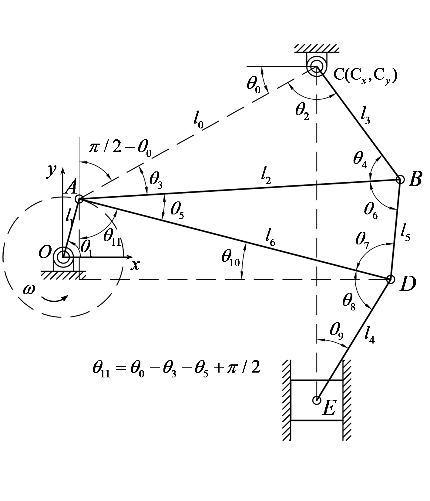
⒜ Knuckle press
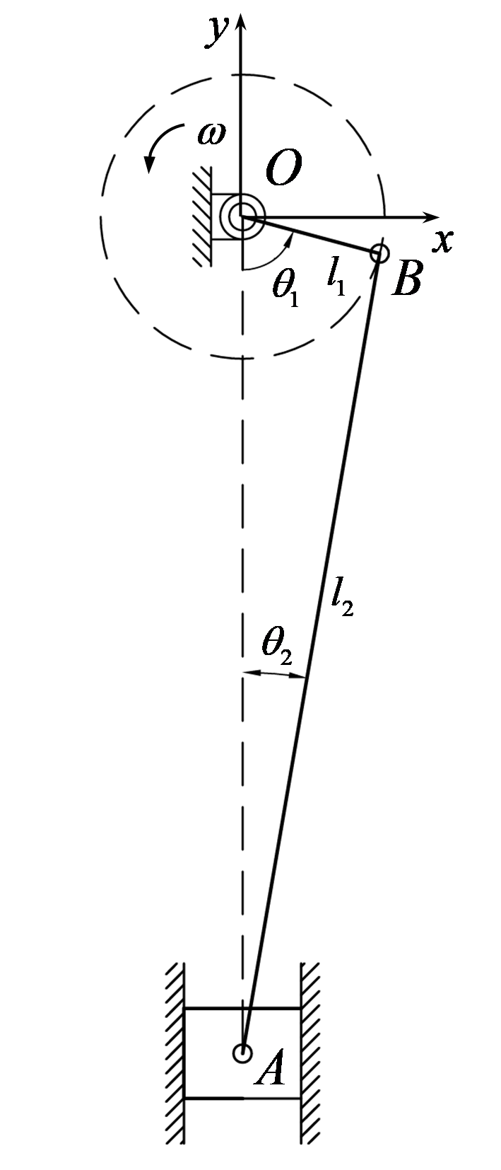
⒝ Slider-crank press
Figure 13.1 Mechanisms of major forging presses
From the standpoint of metal forming simulation, the position and speed of point \(E\) are of primary interest, and the position and speed of this point are expressed as functions of the crank angle and angular velocity, respectively, through kinematic analysis. Since the equations are complex, the presentation of these functional relationships is omitted; instead, the motion characteristics of the knuckle press are explained through an application example in Section 13.5.
13.2 Slider-Crank Press
In general, a mechanical press refers to a slider-crank press. The slider-crank press is widely used for hot forging. A feature of this press is that the upper die maintains a relatively high speed when it reaches the bottom dead center. Unlike the knuckle press, the contact time in hot forging is short, so it is advantageous in terms of die wear life. Of course, owing to the relatively high speed, a sharp increase in the forming load at the last moment is unavoidable.
Figure 5.26⒝ shows the drive mechanism, and the position and speed of point A can be expressed as functions of the crank angle and angular velocity. Since the expression of the speed and position functions themselves is not important from the user's standpoint, this is replaced here by the explanation of the motion characteristics of the slider-crank press in Section 13.5.
13.3 Hammer Press
Hammer forging is on a gradual decline in application owing to environmental and quality issues. However, it still has advantages in the forging of large products. A hammer press is basically a forging machine that uses energy derived from pneumatic pressure and the weight of the hammer. The speed of the punch during forging is determined based on the law of conservation of energy. The counterblow hammer press is intended to impose a large amount of energy on the hammer and die within a limited space, and is used for the production of large forgings.
The energy source of hammer forging consists of the kinetic energy of the hammer at the initial contact with the workpiece and the energy applied after the initial contact with the workpiece, that is, the energy generated by the self-weight of the hammer and the external force applied by the press and the like. Of course, the kinetic energy of the hammer at the initial contact with the workpiece is the work done by the self-weight of the hammer and the pressure of the press from the topmost position to the initial contact. The stroke of the hammer after the initial contact with the workpiece is shorter than the preceding stroke, that is, the stroke for increasing the kinetic energy of the hammer. Therefore, most of the energy depends on the kinetic energy of the hammer at the initial contact with the workpiece. Accordingly, the initial speed is larger than that of press forging.
The energy during hammer forging is dissipated not only into the plastic deformation of the workpiece but also in the form of noise, structural vibration, friction, and the like. The ratio of the energy used for the fundamental purpose of plastic deformation to the total energy is defined as the energy efficiency \(\eta\). The energy efficiency is mainly greatly affected by the contact area; it decreases almost linearly as the contact area increases, and it is reasonable to consider that, depending on the capacity of the hammer forging machine, there exists a critical forging contact area \(A_{cr}\) at which the energy efficiency becomes zero. This is because an increase in area is accompanied by a sharp increase in the forging load and elastic deformation of the forging equipment. Therefore, when the contact area is denoted by \(A_c\), the energy efficiency is expressed by the following equation.
Now let us determine the speed of the hammer. The initial energy \(E_0\) possessed by the hammer is
and under the condition that all of this is converted into kinetic energy, the initial speed can be obtained from the following equation.
Here, \(h\) denotes the stroke of the hammer, and \(m\), \(g\), \(p\), \(A\) denote the mass, gravitational acceleration, cylinder pressure, and cylinder area, respectively. And in a counterblow hammer forging machine the value of \(H\) is 0, while in an ordinary hammer forging machine the value of \(H\) is 1. The energy \(E_i\) and speed \(v_i\) possessed by the hammer at the \(i\)-th analysis step during the analysis are obtained from the following equations.
Here, \(\Delta E_{i-1}\) is the amount obtained by subtracting the energy applied by the self-weight and hydraulic/pneumatic pressure from the energy consumed in the process analysis immediately before the \(i\)-th analysis step, and \(\eta_i\) is the efficiency at the \(i\)-th analysis step.
13.4 Hydraulic Press
A mechanical press does not stop operating until the energy stored in the press is exhausted, unless it has a load-limiting device; a hydraulic press, however, operates within the load limit, that is, within the limit forming load range. This is because the forming load of a hydraulic press is determined by the product of the internal cylinder pressure and the internal cross-sectional area. Of course, the energy that a hydraulic press can form in a single stroke is also regulated. In a hydraulic press, the accumulator, which corresponds to the flywheel of a mechanical press, stores energy during idling. Consuming energy beyond this in a single stroke is normally impossible.
In hot forging, because the workpiece is speed-dependent, the forming load is greatly reduced at low speed. When performing hot forging with a hydraulic press, if it is driven at a speed exceeding the limit forming load of the hydraulic press, the actual process maintains the limit forming load, while the speed of the upper die becomes lower than the desired speed, and the speed itself becomes an unknown. Reflecting this, the metal forming simulator can, at the user's request, calculate the speed of the upper die that satisfies the condition of the limit forming load. In this case, when the upper limit of power becomes a concern, a speed calculation that takes power into account is also possible.
13.5 Influence of Speed
Viscous materials are affected by the strain rate. When the temperature of a metallic material reaches half or more of its melting point, the influence of viscosity becomes dominant.
In general, when analyzing hot forging processes, the die speed is often assumed to be constant. A constant-speed condition is numerically more stable. If the speed imposed on the die changes at every analysis step, solving the nonlinear equations may become correspondingly more difficult. However, since the die speed at the very last moment, that is, at the bottom dead center, must be zero, the constant-speed condition differs greatly from reality, and it is necessary to observe its influence in detail from the standpoints of the deformed shape and the forming load.
For this purpose, the predicted results considering the speed conditions of the knuckle press and the slider-crank press are compared with the predicted results obtained by assuming that the die speed is constant at their average value. The test process in Figure 13.2⒜ is an axisymmetric upsetting process, and an isothermal analysis was performed to focus solely on the influence of speed. The main process information is as follows. Workpiece size: (diameter) 90.0, (height) 120.0 mm; workpiece and flow stress: SCr420HB, Figure 5.27⒝; initial workpiece temperature: 1150; friction condition between workpiece and die: Coulomb friction law (friction coefficient, \(\mu = 0.2\)). The flow stress curve in Figure 13.2⒝ was obtained from compression test results.
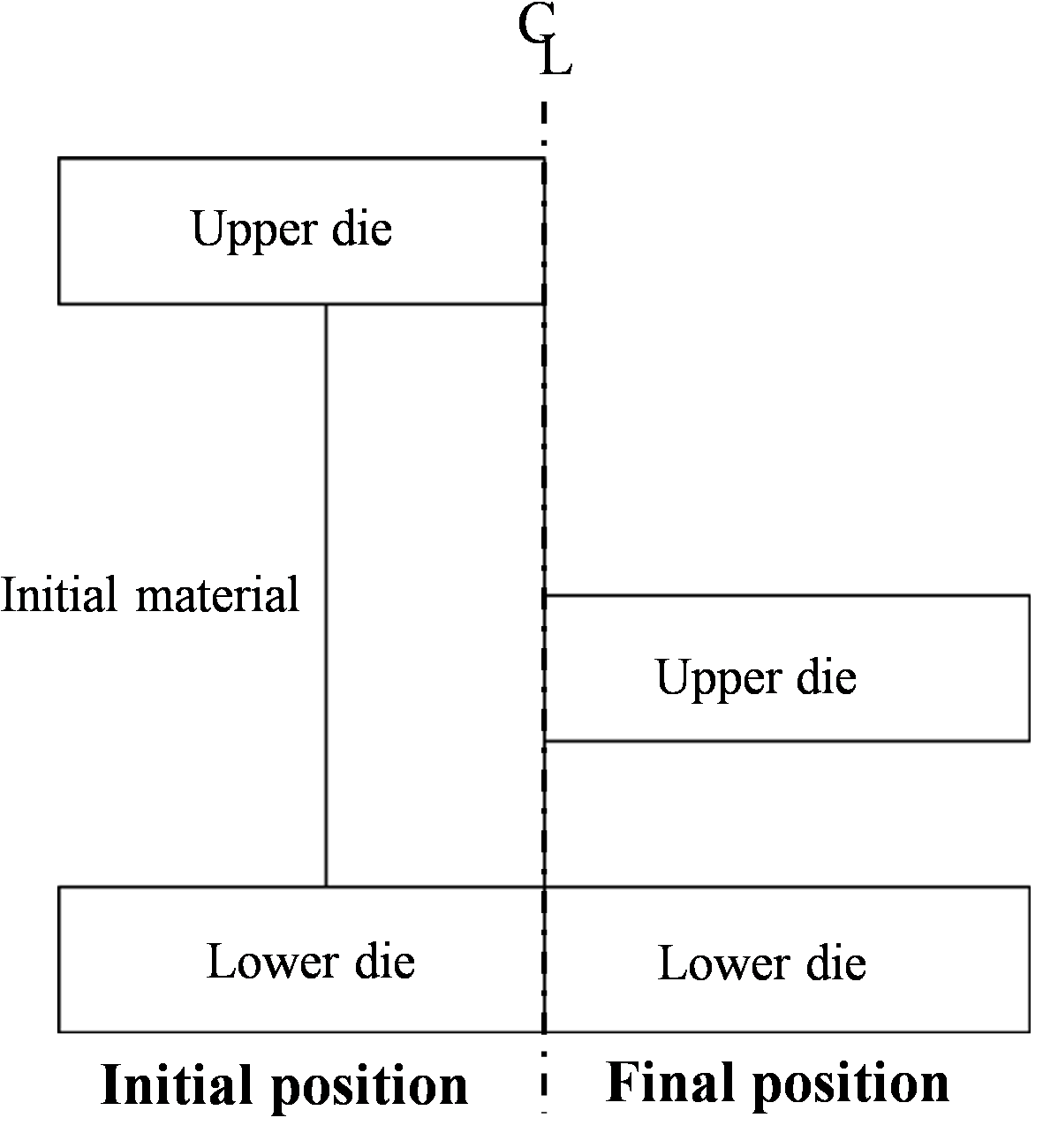
⒜ Test process
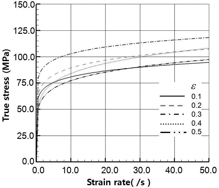
⒝ Flow stress
Figure 13.2 Test process information
The lengths of the members that determine the drive mechanism of the knuckle press are \(l_1 = 150.0\)mm, \(l_2 = l_6 = 800.0\)mm, \(l_5 = 250.0\)mm, \(l_3 = l_4 = 350.0\)mm, and the position of point \(C\) in Figure 13.1(a) is \((C_x, C_y) = (630.0, 475.0)\). The conditions of the slider-crank press are \(l_1 = 150.0\)mm, \(l_5 = 900.0\)mm. The angular velocity of the crank was determined so that the maximum speeds of the two presses would be identical.
Under the aforementioned conditions, the maximum speed determined by considering the stroke is 500 mm/s, as shown in Figure 13.3, so the speed under the constant-speed condition was assumed to be 250 mm/s. And an analysis was performed under an initial constant-speed condition of 250 mm targeting a hydraulic press whose limit forming load is 280 tons. The constant-speed condition of the hydraulic press may be automatically changed to a constant-load-applied condition if the forming load exceeds the limit forming load during the analysis run.
It should be emphasized here that the press conditions used in this section are not actual conditions, and their purpose is to relatively compare the motion characteristics of each press.
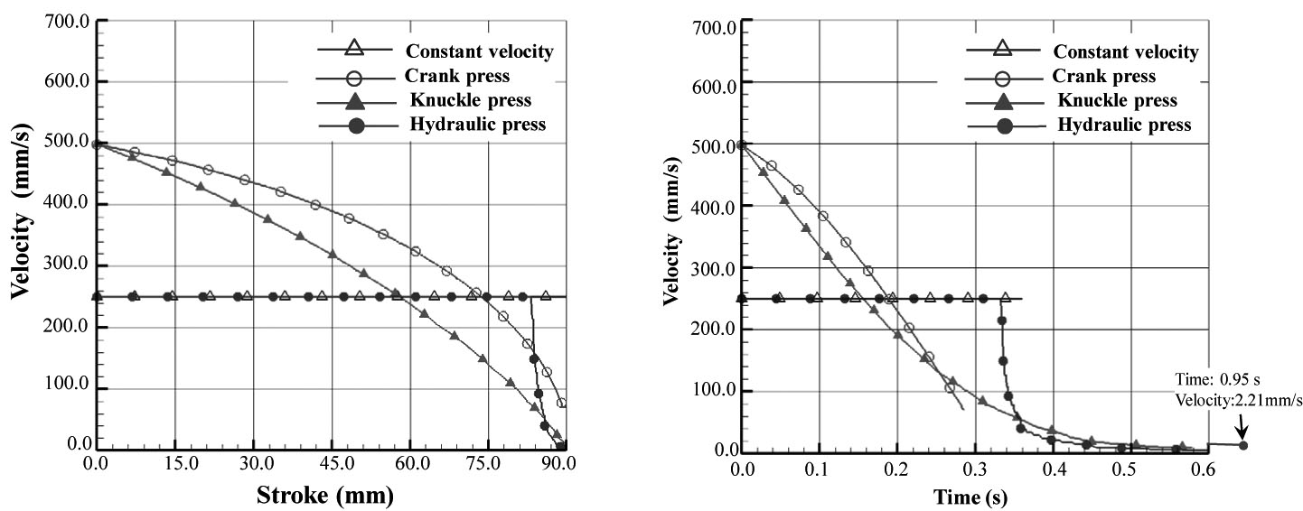
Figure 13.3 Speed diagrams
Figure 13.4 compares the plastic flow lines when the upper die reaches the bottom dead center. The percentage of the maximum radius under the four speed conditions is 0.005%.
And Figure 13.5 compares the forming loads. Under the constant-speed condition, the load increases continuously, whereas in the knuckle press the load stagnates upon reaching the final stage. As a result, a forming load difference of about 21% is ultimately observed between the two presses.
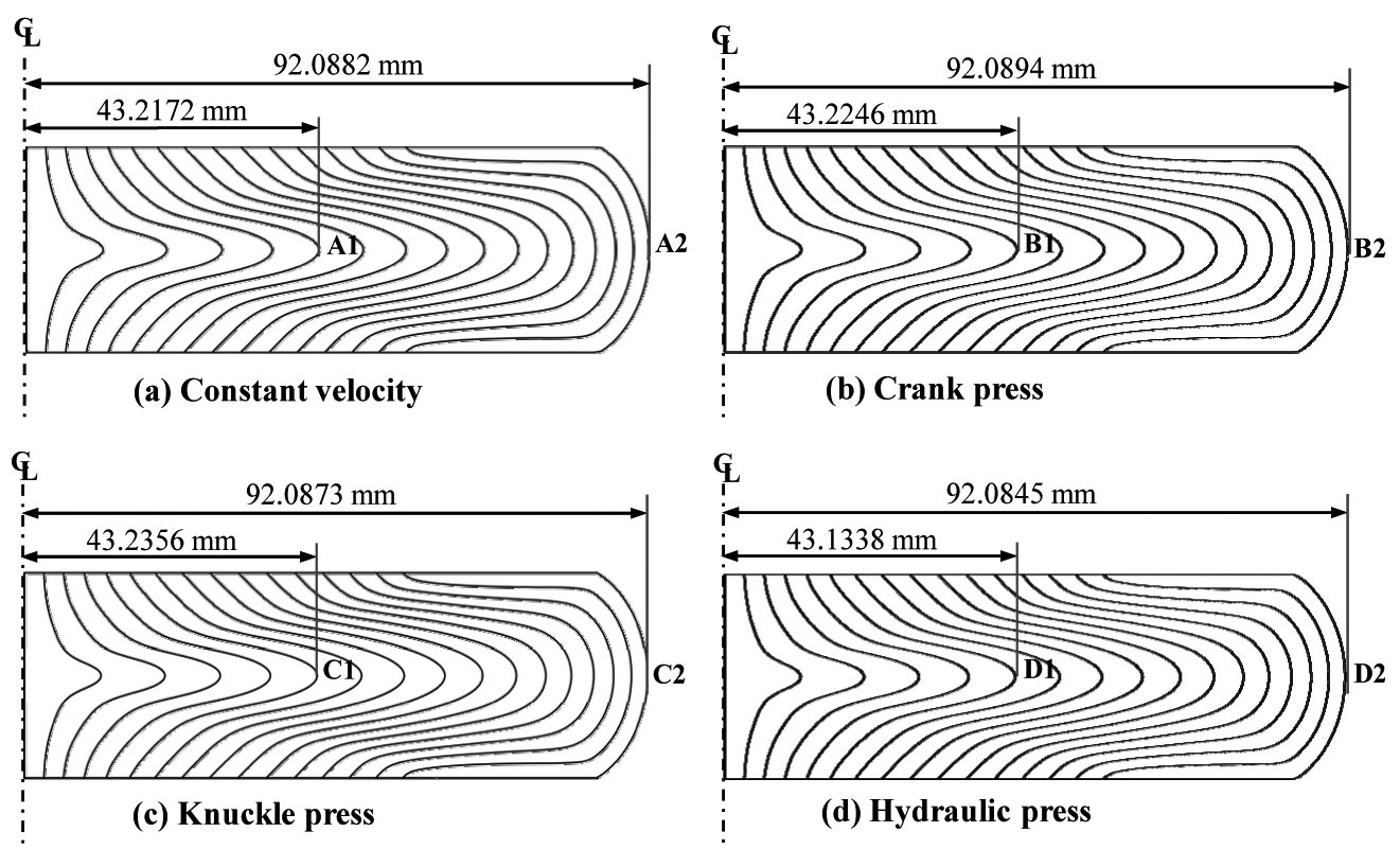
13.4 Comparison of plastic flow lines by press
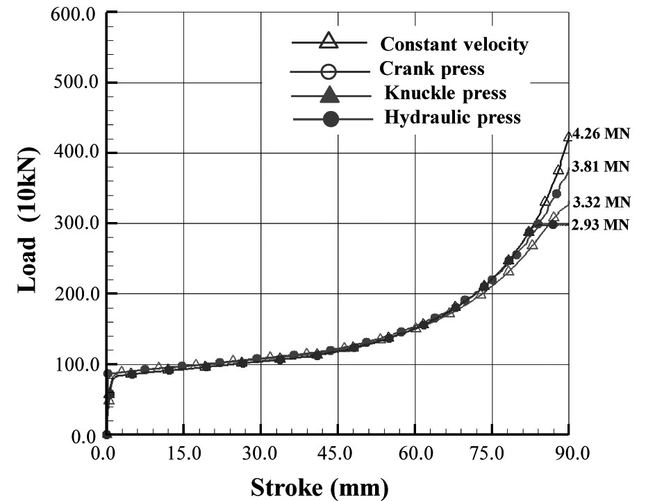
Figure 13.5 Comparison of forming loads by press